
Federating Three MEP Disciplines Across Seven Floors at LOD 300

BIM & Digital Engineering
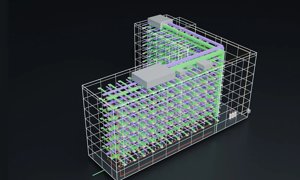
The coordinated building model. Right: the federated MEP systems shown inside the building envelope, with plumbing, HVAC, and hydronic/gas piping in their coordinated positions. Representative model shown; project details have been changed to protect client confidentiality.
- Healthcare Clinic
- Winnipeg, Canada
- MEPF BIM Coordination
Case Study Summary
Service | BIM & Digital Engineering — multidisciplinary MEPF coordination |
Building Type | Healthcare clinic (outpatient), 7 storeys |
Level of Development | LOD 300 |
Disciplines Modeled | Plumbing & drainage · HVAC & air distribution · Hydronic & gas piping |
Software | Autodesk Revit (modeling) · Autodesk Navisworks (federation & clash detection) · AutoCAD (schematic reference) |
Deliverables | Federated .NWD, .NWC coordination cache, .DWG 2D/3D exports |
The Challenge
A seven-storey outpatient healthcare clinic has to fit a dense network of plumbing, HVAC, and hydronic and gas systems into fixed structural limits, under the tight spatial and life-safety tolerances that healthcare facilities carry. Exam rooms, treatment rooms, and washrooms on every floor put plumbing fixtures across the whole floor plate, so sanitary drainage needs consistent gravity fall with no room to compromise on slope. HVAC ductwork needs real clearance in the ceiling zone, and hydronic and gas lines need rule-compliant terminations at the rooftop mechanical room. All three were competing for the same limited ceiling and shaft space across seven floors, designed by different trades on different drawings, with no single view of how they’d actually fit together until installation.
Our Approach
Each MEP discipline — plumbing & drainage, HVAC & air distribution, and hydronic & gas piping — was modeled independently first, at full fidelity, before any spatial coordination began. That let each system be checked on its own terms first: correct fall on gravity drainage, real clearance around duct fittings and access panels, correct termination detailing on gas lines.
Space was allocated by priority, not by modeling convenience: plumbing drainage — which relies on gravity and can’t be rerouted around an obstruction after the fact — was given priority in the lower ceiling zone, with HVAC’s larger-profile ductwork routed through the zone above it. That sequencing decision, made before modeling even started, heads off the more common failure mode: routing HVAC first because it’s usually modeled first, then discovering drainage has nowhere left to fall correctly.

The plumbing, drainage, and vent piping system modeled in isolation, before being brought into the federated model.
Once each isolated system was validated, all three were aggregated into a single federated model in Navisworks, where clash detection surfaced interferences between systems (most importantly between large duct runs and gravity-fed drainage) while there was still time to resolve them on screen instead of on site. Every run was tracked continuously across all seven floors and up to the roof to catch disconnected fittings or orphaned pipe segments before handoff.
Results
7
Floors coordinated in one federated model
LOD 300
Delivered across every modeled discipline
3
MEP systems modeled independently, then federated
The federated model gave the design and construction team a single, coordinated source of truth for how plumbing, HVAC, and hydronic/gas systems actually occupy the building — not just where each discipline intended to route, but where all three fit together in the same physical space. Maintenance clearances, equipment footprints, and valve access were checked directly against the model rather than assumed from separate, uncoordinated drawings.

The fully federated MEP model, with plumbing, HVAC, and hydronic/gas systems shown together and color-coded by discipline, ahead of construction.
Why It Matters for Your Project
Coordinating each discipline individually before federating them catches the clashes that matter most, the ones between systems and not just within one, while they’re still cheap to resolve on screen. For a project team, that means fewer conflicts discovered in the field, a bill of quantities that comes from a model built to true size and location rather than a manual takeoff, and confidence that maintenance access was designed in rather than discovered missing after installation. That’s the same coordination discipline our BIM team brings to every multidisciplinary project, whether it’s a seven-storey clinic or a larger, more complex facility.